

What is an Optical Splitter?
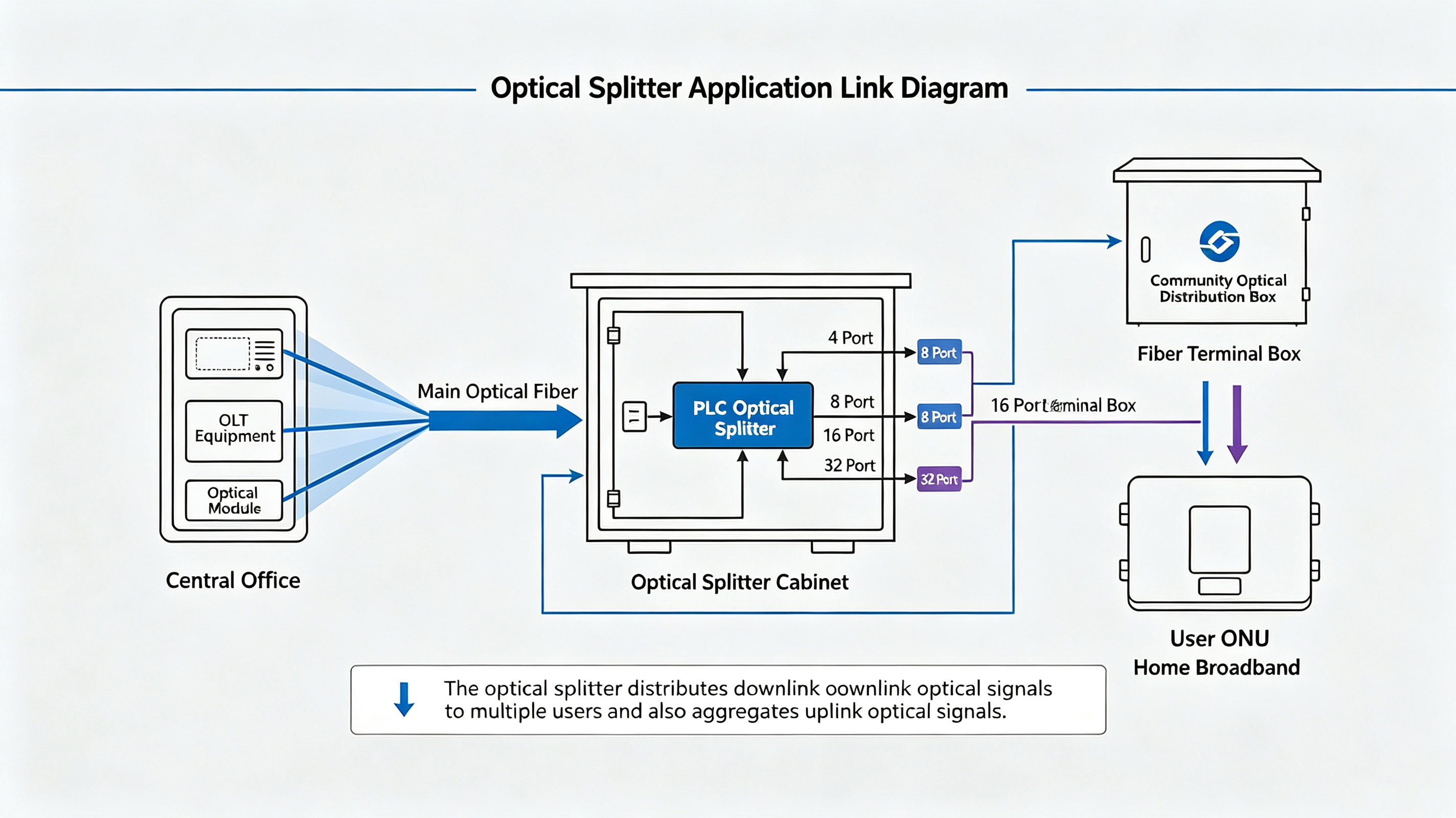
An optical splitter is a passive optical component. Its core task is simple and pure: to distribute the optical signal from a single input fiber to multiple output fibers according to a preset ratio (e.g., equally or unequally); conversely, it can also combine optical signals from multiple fibers into a single fiber.
To use a plumbing analogy, it is the "three-way diverter valve" of the optical network — dividing the water from one "optical canal" evenly into dozens of smaller "canals" flowing to thousands of households.
To thoroughly explain it, I will break it down from three dimensions: underlying process, core parameters, and practical selection.
I. Two Major Process Types: FBT vs. PLC (The First Selection Criterion)
Optical splitters on the market fall into two categories based on manufacturing process, with vastly different performance characteristics; choosing the wrong type can directly impact link budget:
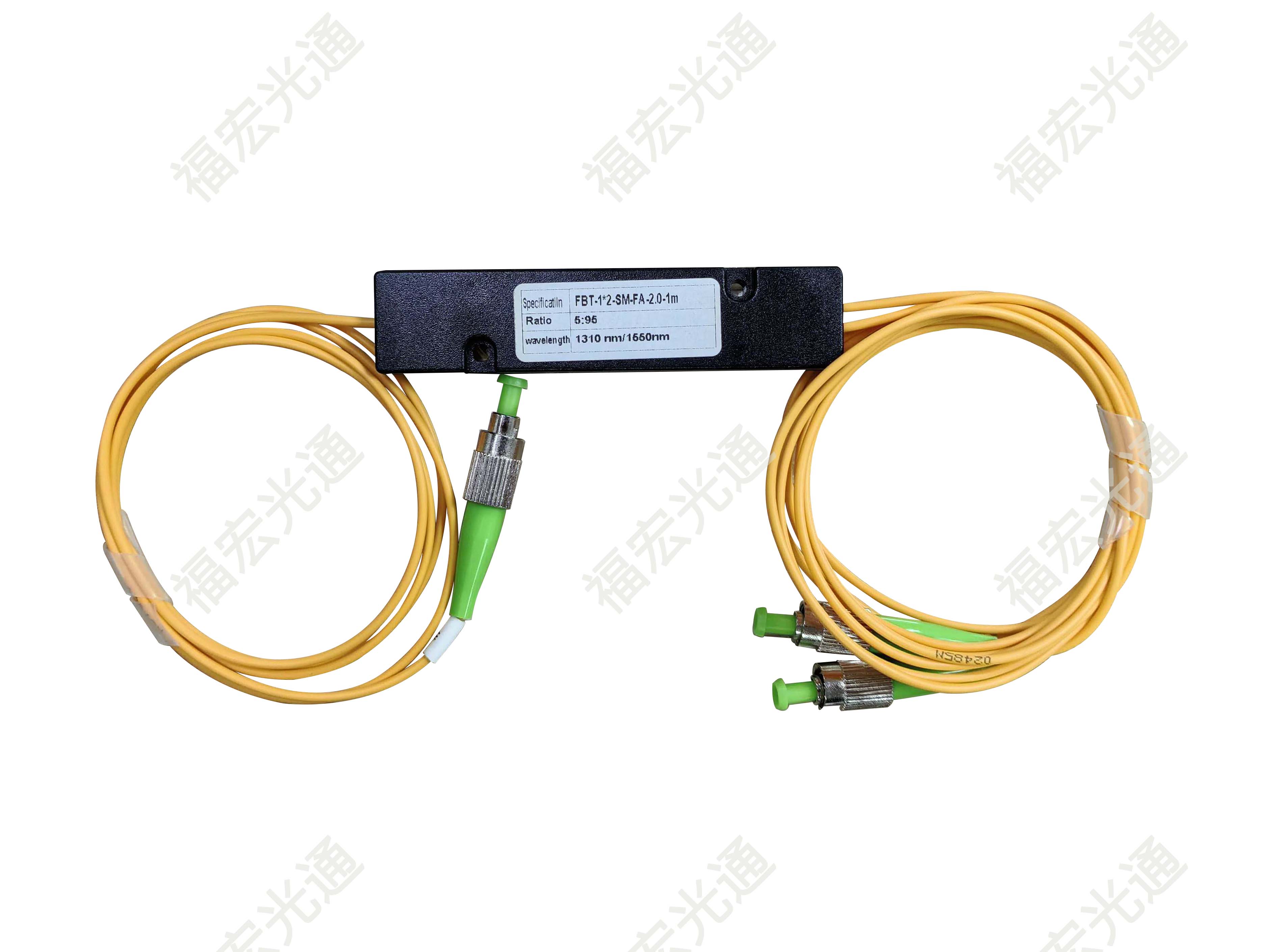
1. FBT (Fused Biconical Taper) — Traditional Technique
- Principle: Two or more fibers are bundled together and fused under high temperature while being stretched. The coupling ratio is varied by controlling the stretch length.
- Characteristics: Low cost, flexible splitting ratios (e.g., non‑standard ratios like 5:95, 20:80). The splitting ratio is highly wavelength‑dependent (inconsistent splitting at different wavelengths), and packaging is typically in narrow strip‑type cases. Currently mainly used in split‑monitoring systems and other unequal‑split systems.
2. PLC (Planar Lightwave Circuit) — The Current Absolute Mainstream
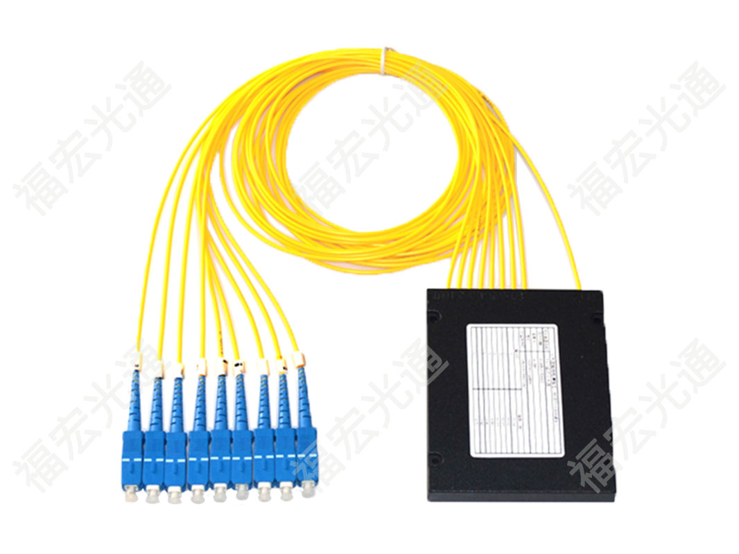
- Principle: Uses semiconductor lithography to etch Y‑branch waveguide arrays on a silica glass substrate. Optical signals are precisely split via the lithographically defined paths.
- Characteristics: Excellent splitting uniformity (e.g., 1×32 uniformity can be controlled within ±0.5 dB), compact size, and wavelength‑insensitive (flat across 1260 nm–1650 nm). Today, PLC splitters are almost exclusively used in FTTH and PON networks. Fholink's high‑performance PLC splitters are widely deployed in HTTX passive optical networks.
II. Core Performance Metrics (Understanding the Datasheet)
- Split Ratio: The most common configurations are 1×N (one input, N outputs) or 2×N (dual inputs, N outputs, used for main/backup protection). Common specifications: 1×4, 1×8, 1×16, 1×32, 1×64.
- Insertion Loss (IL) — A Core Pain Point: This is the power attenuation introduced by the device. Note: many mistakenly think the theoretical loss for a 1×32 equal split is 10*log10(1/32) = 15 dB, but that is the theoretical value. In practice, insertion loss = theoretical splitting loss + additional excess loss. A good PLC manufacturer (like Fholink's standard products) can keep total 1×32 loss within 16.5 dB (including connector loss). Every 0.5 dB reduction means the OLT can support an additional several hundred meters of reach.
- Uniformity: The maximum loss difference among all output ports. Poor uniformity (e.g., >1.5 dB) can cause users close to the OLT to receive excessively strong light (damaging the receiver) while those farther away get too weak a signal to power on. High‑quality PLCs should achieve uniformity ≤ 0.8 dB.
- Polarization Dependent Loss (PDL): Loss fluctuations due to different polarization states of the incident light. In high‑speed coherent systems, high PDL degrades OSNR; engineering requirements typically demand PDL ≤ 0.2 dB.
III. Core Functions and Scenarios (The "Neural Network Node" of Optical Networks)
Optical splitters are not merely for "splitting light"; they play two irreplaceable strategic roles in modern networks:
1. Physical‑Layer "Hard‑Slice" Capacity Multiplication (Core of PON Networks): In passive optical networks (PON/GPON/XGS‑PON), the central OLT transmits a single 2.5G or 10G optical signal, which after a 1×64 splitter simultaneously feeds 64 households. This is the fundamental reason fiber broadband can achieve "one fiber to the home" at low cost — the splitter requires no power, has an extremely low failure rate, and truly enables passive green access.
2. "Probe" for Optical Path Monitoring (Essential for OTDR Testing): In backbone maintenance, engineers insert an unequal‑ratio splitter (e.g., 99%/1%) at the link head‑end. The 1% branch is used to extract a small optical signal to a monitoring port, connected to an OTDR or optical power meter for real‑time online monitoring of attenuation and breakpoints along the entire backbone, without affecting the 99% main optical path.
IV. Package Forms Determine Installation Costs
Fholink offers different packages based on customer scenarios:
- Micro‑Module (Bare‑fiber type, ~3×3 mm): For tight optical distribution boxes or ODF frames, fused directly in protective sleeves.
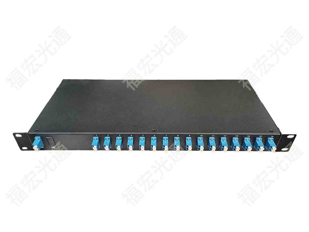
- Rack‑mount / Plug‑in type (1U or 2U chassis): For data centers or large base stations, equipped with removable connectors (SC/APC or FC/UPC) for flexible patching.
- Box‑type (with pigtails): For outdoor ground‑level cross‑connect cabinets, with high protection ratings and strong tensile strength.
In summary: Optical splitters are the cornerstone for optical networks to evolve from "point‑to‑point" to "point‑to‑multipoint." They do not emit light, amplify signals, or process data, but they release a single fiber's bandwidth potential to countless end users in the most physical and reliable way.


