

Optical Filter
An optical filter is essentially a wavelength selector or "frequency gate." Its core function is to precisely extract a specific wavelength from a mixed optical signal containing multiple wavelengths, while blocking or filtering out other wavelengths.
You can think of it as a light‑based "sieve" or "spectral prism." In Wavelength Division Multiplexing (WDM) technology—which "bundles" multiple wavelengths into a single fiber for transmission—optical filters are responsible for combining different wavelengths at the transmitting end and for precisely separating them at the receiving end.
To fully understand optical filters, we need to break them down from two dimensions: **Function** and **Principle of Operation.
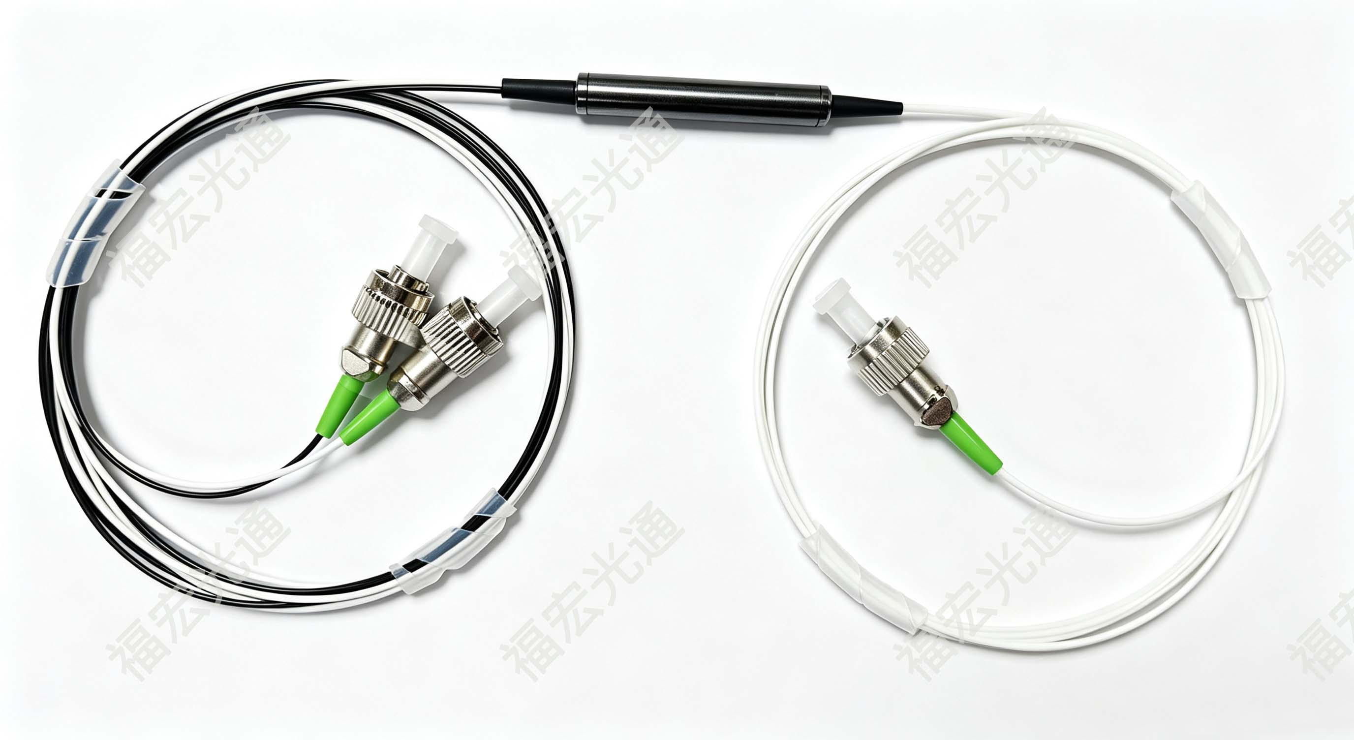
I. Five Core Functions of Optical Filters (Engineering Value)
In the products delivered by Fholink Technology, optical filters are by no means isolated components; they are powerful tools for solving the following five specific engineering pain points:
1. Wavelength Multiplexing / Demultiplexing (MUX/DEMUX) — Core Mission: In DWDM/CWDM systems, the transmitting end combines multiple optical signals of different wavelengths into a single fiber (multiplexing); the receiving end separates the mixed light back into individual wavelengths (demultiplexing). Without filters, a single fiber could only carry one wavelength, making resource utilization extremely low.
2. ASE Noise Suppression (Improving OSNR): Erbium‑Doped Fiber Amplifiers (EDFAs) generate broadband spontaneous emission noise (ASE) during operation. By cascading an optical filter after the amplifier, out‑of‑band noise is filtered out like a "sieve," improving the Optical Signal‑to‑Noise Ratio (OSNR) by 3–5 dB and directly extending the transmission distance.
3. Gain Flattening: EDFAs naturally have uneven gain across the C‑band (higher gain near 1528 nm, lower near 1560 nm). A Gain Flattening Filter (GFF) is used to compensate inversely, making the output power of each channel more uniform—an unsung hero in long‑haul transmission.
4. Channel Isolation (Preventing Adjacent Channel Crosstalk): In dense WDM systems, adjacent channel spacing is only 0.4 nm (50 GHz). Filters provide very high adjacent channel isolation (typically >25 dB), ensuring that light from Channel A does not "leak" into the receiver of Channel B.
5. Optical Performance Monitoring (OPM): In an Optical Supervisory Channel (OSC), a filter splits out 1%–5% of a specific wavelength for real‑time detection of link loss and power, without affecting the main service optical path.
II. Operating Principles of Four Major Technology Routes (Physical Fundamentals)
The wavelength selectivity of optical filters fundamentally relies on the physical effects of light‑matter interaction. There are four mainstream implementation methods in the industry today, each based on distinctly different principles:
1. Thin‑Film Filter (TFF) — The Most Mature "Multi‑Layer Interference"
- Operating Principle: Based on multi‑beam interference. On a glass substrate, dozens or even hundreds of alternating layers of high‑ and low‑refractive‑index dielectric films (such as Ta₂O₅ and SiO₂) are deposited. Each layer thickness is precisely controlled to a quarter of the target wavelength.
- When light enters the stack, specific wavelengths satisfying the Bragg condition (`2nd = mλ`) experience constructive interference and pass through efficiently (transmission); other wavelengths undergo destructive interference and are reflected back. By designing the layer structure and stacking sequence, the filter can be made as band‑pass (letting specific wavelengths through), band‑stop (blocking specific wavelengths), or splitter (transmitting A and reflecting B).
- Engineering Characteristics: Extremely low insertion loss (<0.3 dB), excellent temperature stability (<0.001 nm/℃), making it the workhorse for DWDM channel separation.
2. Fiber Bragg Grating (FBG) — A "Mirror" Inside the Core
- Operating Principle: Uses UV laser to inscribe a series of periodic permanent refractive‑index changes (the grating) into the core of a single‑mode fiber. It follows the Bragg reflection law: `λ_B = 2 · n_eff · Λ` (where `n_eff` is the effective refractive index and `Λ` is the grating period).
- When broadband light enters the FBG, only the extremely narrow wavelength satisfying this condition (linewidth can be as small as 0.01 nm) is reflected back by the core grating; all other wavelengths pass through unaffected.
- Engineering Characteristics: Extremely high wavelength selectivity, naturally compatible with optical fibers, commonly used for making ultra‑narrowband reflection‑type filters and dispersion compensators.
3. Arrayed Waveguide Grating (AWG) — "Grating Spectroscopy" on a Planar Platform
- Operating Principle: Fabricated on a PLC (Planar Lightwave Circuit) chip using semiconductor lithography. Its structure includes input waveguides, an input star coupler, an array of waveguides with linearly increasing length differences (ΔL), an output star coupler, and output waveguides.
- Different wavelengths diffract in the input star coupler and enter the array waveguides. Due to the fixed optical path difference (ΔL) between adjacent waveguides, different wavelengths interfere at the output star coupler and are focused onto different output ports. This is equivalent to a spatial "wavelength‑to‑position" mapping.
- Engineering Characteristics: Monolithically integrated, with very high channel counts (up to 80 channels or more), suitable for large‑scale DWDM systems, but temperature‑sensitive and requires thermal control (TEC).
4. Fabry‑Pérot (F‑P) Tunable Filter — Resonant Cavity Frequency Selection
- Operating Principle: Composed of two high‑reflectivity parallel mirrors forming an optical resonant cavity (air gap or solid). Incident light reflects back and forth within the cavity, creating multi‑beam interference.
- Only light wavelengths satisfying the resonance condition `2 · n · L · cosθ = m · λ` (where L is the cavity length) can build up in the cavity and be transmitted. By using a piezoelectric transducer (PZT) or MEMS mirror to change the cavity length L, the transmission wavelength can be continuously tuned.
- Engineering Characteristics: The only wavelength‑tunable filter (tuning range up to 40 nm), with fast response, but with a relatively wide bandwidth, suitable for spectral analysis and coarse scanning.
III. Core Parameters
|
Parameter |
Physical Meaning |
Engineering Requirements |
|
Insertion Loss (IL) |
Power loss of the useful signal passing through |
The lower the better; typical value for channel filters < 1.0 dB |
|
Isolation |
Suppression of non‑target wavelengths |
Adjacent channel isolation > 25 dB; non‑adjacent channel > 40 dB |
|
Passband Bandwidth (BW) |
Effective frequency width allowed to pass |
0.4 nm @ -0.5 dB bandwidth for 50 GHz spaced systems; 0.8 nm for 100 GHz spaced systems |
Summary
Optical filters perform "wavelength routing" and "noise purification" at the physical layer of optical networks. Their operating principles rely on four fundamentally different physical mechanisms: interference (TFF), diffraction (FBG), interferometric arrays (AWG), and resonance (F‑P). In Fholink Technology's DWDM systems and EDFA modules, we combine these technologies according to different scenarios to achieve optimal link budget and transmission quality.


