
Three-Loop Polarization Controller (TPC)
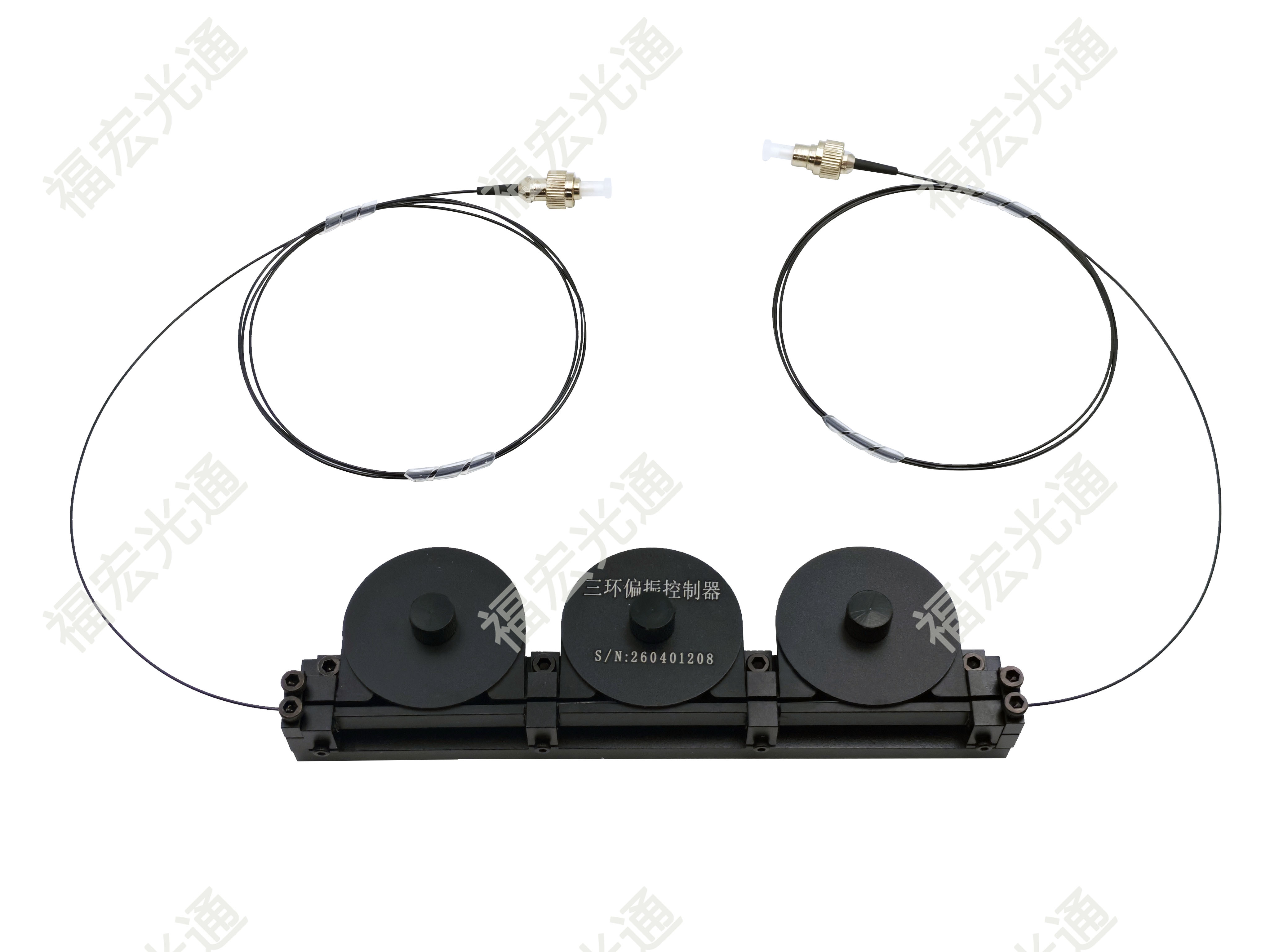
The Three-Loop Polarization Controller (TPC), also known as a three-loop fiber polarization controller or three-paddle polarization controller, is an all-fiber, passive, manually adjustable polarization state control device. By mechanically rotating three loops wound with single-mode fiber, it utilizes the stress birefringence effect induced by fiber bending to equivalently implement a cascade of λ/4 + λ/2 + λ/4 waveplates, thereby converting any input polarization state into any desired output polarization state.
Below is a complete product-level breakdown from six dimensions: product structure, operating principle, key parameters, application scenarios, selection guidelines, and product performance.
I. Product Structure: Three Loops, Three "Waveplates"
The Three-Loop Polarization Controller typically appears as a small metal or plastic housing with three independently rotatable dials (paddles). Each dial has several turns of single-mode fiber wound around it. The diameters and winding turns of the three loops are precisely designed so that, at the design wavelength, they are equivalent to:
|
Loop No. |
Equivalent Waveplate |
Phase Retardation |
Main Function |
|
First Loop |
λ/4 waveplate |
π/2 |
Converts any input polarization state into linear polarization |
|
Second Loop |
λ/2 waveplate |
π |
Rotates the linear polarization direction to the target angle |
|
Third Loop |
λ/4 waveplate |
π/2 |
Converts linear polarization into the target output polarization state |
All three loops can rotate continuously 360°, and the rotation angle corresponds to the change in the azimuth of the waveplate's optical axis. This "λ/4 → λ/2 → λ/4" cascade structure is a classic scheme for achieving arbitrary polarization transformation in polarization optics.
II. Operating Principle: Stress Birefringence + Jones Matrix Cascade
When an optical fiber is wound into a loop, the outer side is stretched and the inner side is compressed, generating stress birefringence. The two orthogonal polarization components experience different effective refractive indices, thereby producing a phase difference. The phase retardation of a single loop can be approximately expressed as:
φ = a · N · d² / (λ · D)
Where: a is the stress birefringence constant, N is the number of winding turns, d is the fiber cladding diameter, λ is the operating wavelength, and D is the loop diameter.
By designing N and D, the first and third loops are made equivalent to λ/4 waveplates at the target wavelength, and the second loop is equivalent to a λ/2 waveplate. Denoting the rotation angles of the three loops as α, δ, and γ respectively, the Jones matrix of the entire device is:
J = J_λ/4(γ) · J_λ/2(δ) · J_λ/4(α)
Since the three azimuth angles are independently adjustable, this matrix can cover all polarization states on the Poincaré sphere. In practice, the first loop is usually rotated first to convert the input light into linear polarization, then the second loop is rotated to adjust the linear polarization direction, and finally the third loop is rotated to generate the desired output polarization state.
III. Key Performance Parameters
|
Parameter |
Typical Value |
Description |
|
Operating Wavelength |
1310 nm / 1550 nm / 1064 nm |
Other wavelengths customizable |
|
Insertion Loss |
≤ 0.3 dB (typical) |
All-fiber structure, extremely low loss |
|
Return Loss |
≥ 60 dB |
Minimal impact on light source |
|
Polarization Dependent Loss |
≤ 0.1 dB |
Low PDL, ensuring control precision |
|
Extinction Ratio |
Adjustable to > 20 dB |
Depends on operating precision |
|
Power Handling |
Standard type ≤ 300 mW |
High-power type customizable to over 1 W |
|
Fiber Type |
SMF-28e or equivalent single-mode fiber |
Polarization-maintaining fiber version also customizable |
|
Connector Type |
FC/APC, FC/UPC, SC/APC, etc. |
Available with pigtails or flanges |
|
Operating Temperature |
-10℃ ~ +70℃ |
Industrial grade customizable to -40℃ ~ +85℃ |
IV. Typical Application Scenarios
1. Fiber Optic Communication and Coherent Systems
Used for polarization state adjustment before coherent receivers, polarization demultiplexing, PMD (Polarization Mode Dispersion) compensation experiments, and polarization-dependent loss (PDL) measurement.
2. Fiber Optic Sensing and Interferometers
In fiber optic gyroscopes, fiber optic current sensors, and Mach-Zehnder interferometers, it precisely controls the polarization states of the two arms, improving interference contrast and sensing stability.
3. Fiber Lasers
As an intracavity polarization control element, it optimizes the polarization extinction ratio and power stability of the output laser.
4. Testing and Measurement
Combined with a polarization analyzer, it performs polarization state scanning, degree of polarization (DOP) testing, and device polarization response characterization.
5. Scientific Research Laboratories
In experiments such as quantum optics, nonlinear optics, and fiber Brillouin scattering, it serves as a low-cost, low-loss polarization adjustment tool.
V. Selection Guidelines
- Wavelength Matching: The waveplate characteristics of the Three-Loop Polarization Controller are wavelength-sensitive. A model consistent with (or close to) the system operating wavelength must be selected. Deviation from the design wavelength causes phase deviation of the equivalent waveplates and degrades control precision.
- Power Handling Capability: Standard models are used for mW-level signal light; for high-power lasers, a high-power version should be selected, with attention to fiber coating and heat dissipation.
- Connector and Fiber Type: Choose FC/APC or FC/UPC based on existing patch cord connectors; if polarization-maintaining transmission is required, select the polarization-maintaining fiber version.
- Manual vs. Motorized: Manual types are low-cost and compact; motorized types can be driven by motors for remote or automatic control, suitable for integration into automated test systems.
- Open-loop vs. Closed-loop: The three-loop manual controller is open-loop and requires an external polarization analyzer for feedback; if automatic polarization locking is needed, an automatic polarization controller based on the three-loop structure or a squeeze-type/electro-optic dynamic controller should be selected.
VI. Product Performance
☆ All-fiber structure, extremely low insertion loss, extremely high return loss
☆ Naturally compatible with fiber optic systems, no free-space optical path alignment required
☆ Low cost, intuitive operation, continuous stepless adjustment
☆ Can cover any polarization state, large adjustment range
☆ Passive device, high reliability, long lifetime
Shenzhen Fholink Technology Co., Ltd. has mature design and manufacturing capabilities in the field of fiber optic passive components. It can provide standard products and customized services for Three-Loop Polarization Controllers, supporting wavelengths such as 1310 nm, 1550 nm, and 1064 nm, with optional FC/APC and FC/UPC connectors, and can adjust fiber type, power handling capability, and operating temperature range according to customer requirements. For scenarios requiring automated control, Fholink Technology can also provide motorized versions and supporting control solutions.
Summary: The Three-Loop Polarization Controller is a classic all-fiber device that uses softness to overcome hardness — it does not rely on complex optical coatings or expensive electro-optic crystals, but instead utilizes the bending stress of the fiber itself to achieve complete control of the polarization state with extremely low loss and high compatibility. It is an indispensable polarization adjustment tool in laboratories and test systems, and also one of the best teaching aids for understanding fiber polarization optics.


